


This tutorial continues on from ATmega8 Breadboard
Circuit – Part 1 where we build a small power supply on the breadboard. In this
part we will add the microcontroller and an interface to allow it to be
programmed.


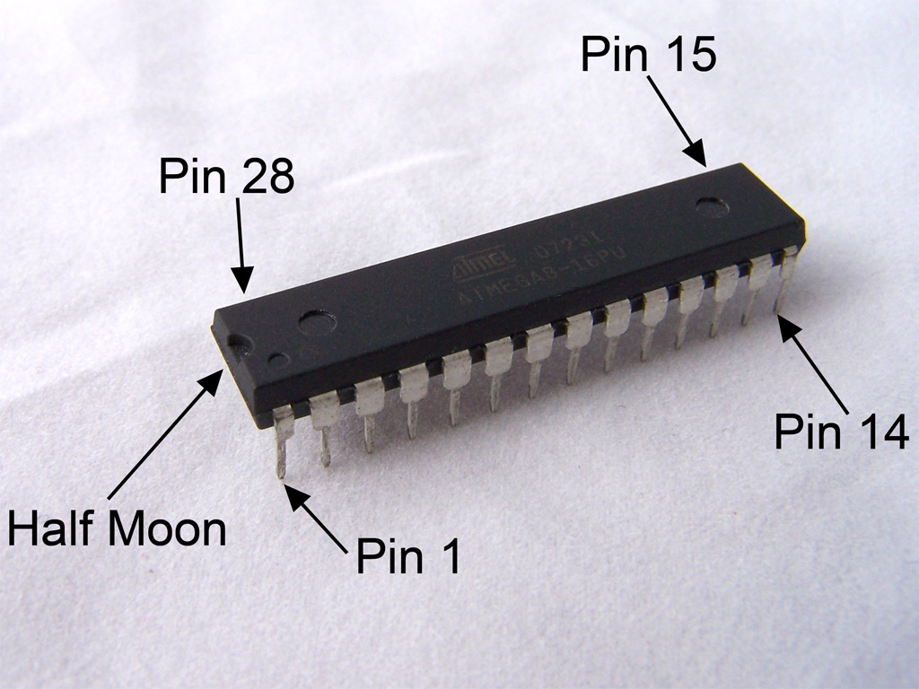
When you look at the microcontroller you will see a few makings which
help identify the pin numbers. At one end there is a semicircle/half moon
section. This denotes the top of the IC (Integrated Circuit). In a PDIP/DIP
package the pins are numbered from 1 in an anticlockwise fashion from this
marker. Additionally, on the ATmega8 there is a small circle identifying pin 1.
When you look at the pin-out, you will notice that many of the pins are
marked as I/O ports. e.g. Pin 28 has the label “PC5”, which means “Port C pin
5”. The I/O ports also have secondary functions which are noted in parenthesis.
e.g. pin 28 has secondary functions of ADC5 (ADC Input Channel 5) and SCL
(Two-wire Serial Bus Clock Line). In some cases (e.g. reset on pin 1), the
secondary function is much more commonly used than the primary function.
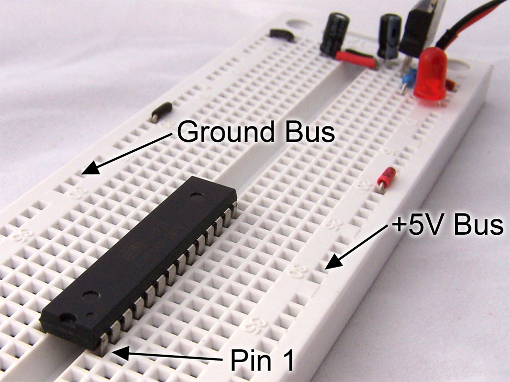
Now it’s time to insert the microcontroller onto the breadboard. You
will need to bend the pins inwards slightly. One method is to insert one side
of the IC in shallowly then bend the pins on the other side so that they fit
into the tie points on that side. You can then gently push/wiggle the IC in.
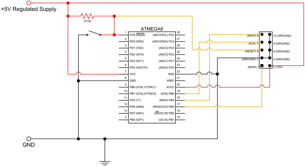
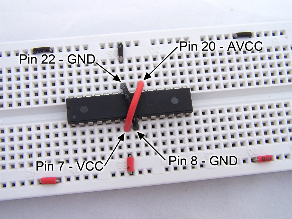
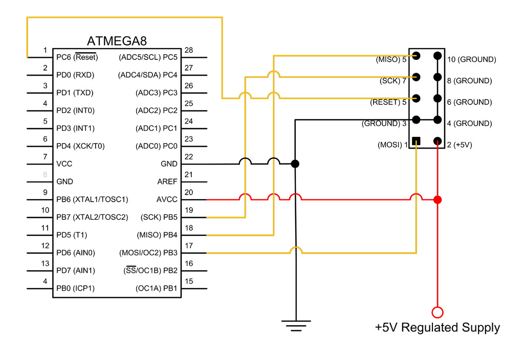
Now we will supply power to the IC. The ATmega8 has 2 ground pins (8
& 22), a VCC pin (7) for positive power supply and an analog VCC pin (20)
to provide power to the AD converter. The figure below shows these connected
up.
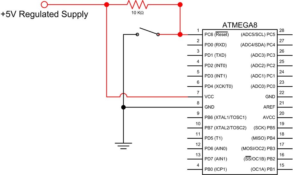
For normal operation, pin 1 (PD0/Reset) needs to be kept high. When this
pin is temporarily grounded, the system resets/reboots. This is indicated in
the pinout diagram by the horizontal line above “RESET”. This notation is quite
common and means the function is activated when the pin is grounded.
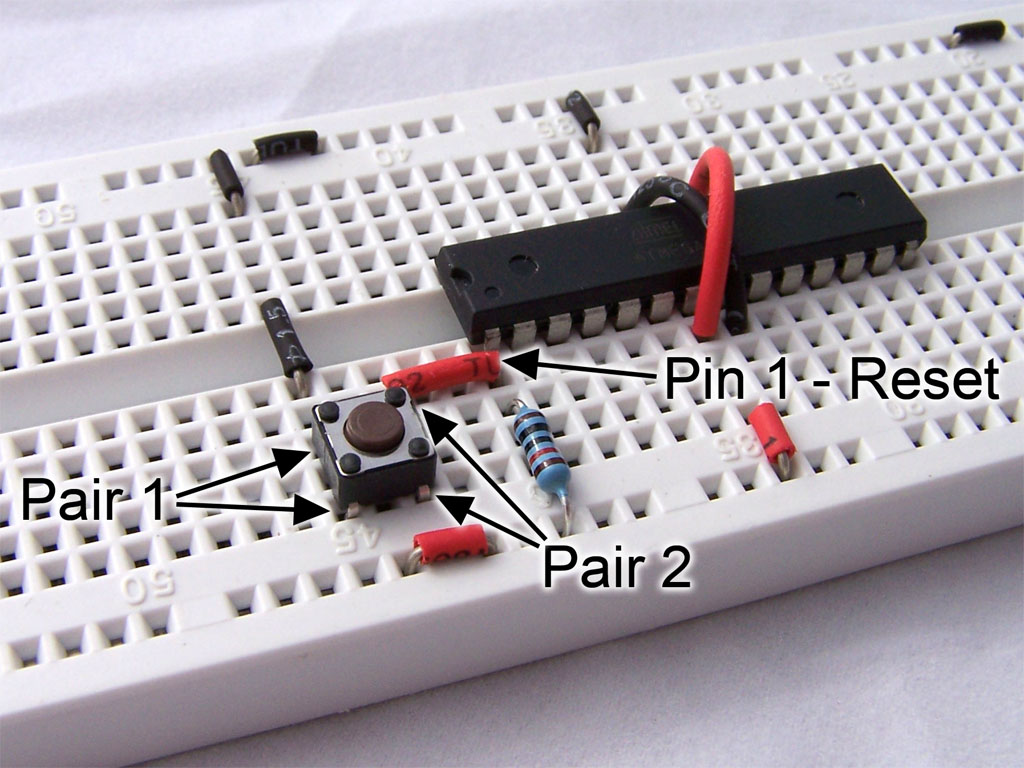
We will build a circuit consisting or a 10k; resistor and a push button
switch. The resistor “pulls up” the pin so that it is high for normal
operation, whilst the pushbutton switch temporarily grounds the pin for the
reset operation. If the resistor wasn’t there (i.e. replaced by a 0 ohm piece
of wire), then pressing the pushbutton would divert all power to ground, which
would mean no power for VCC/AVCC and blowing up the power supply.
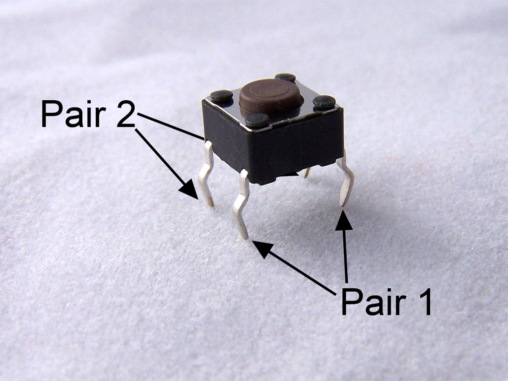
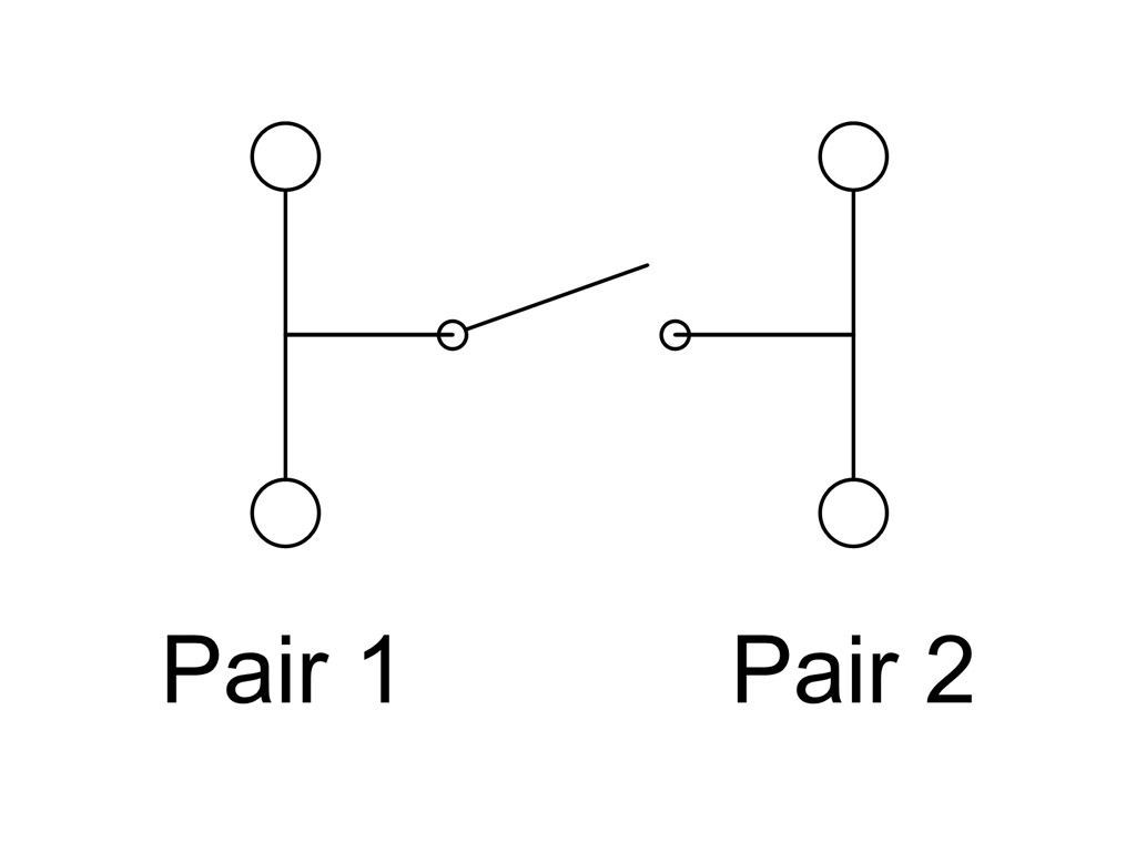
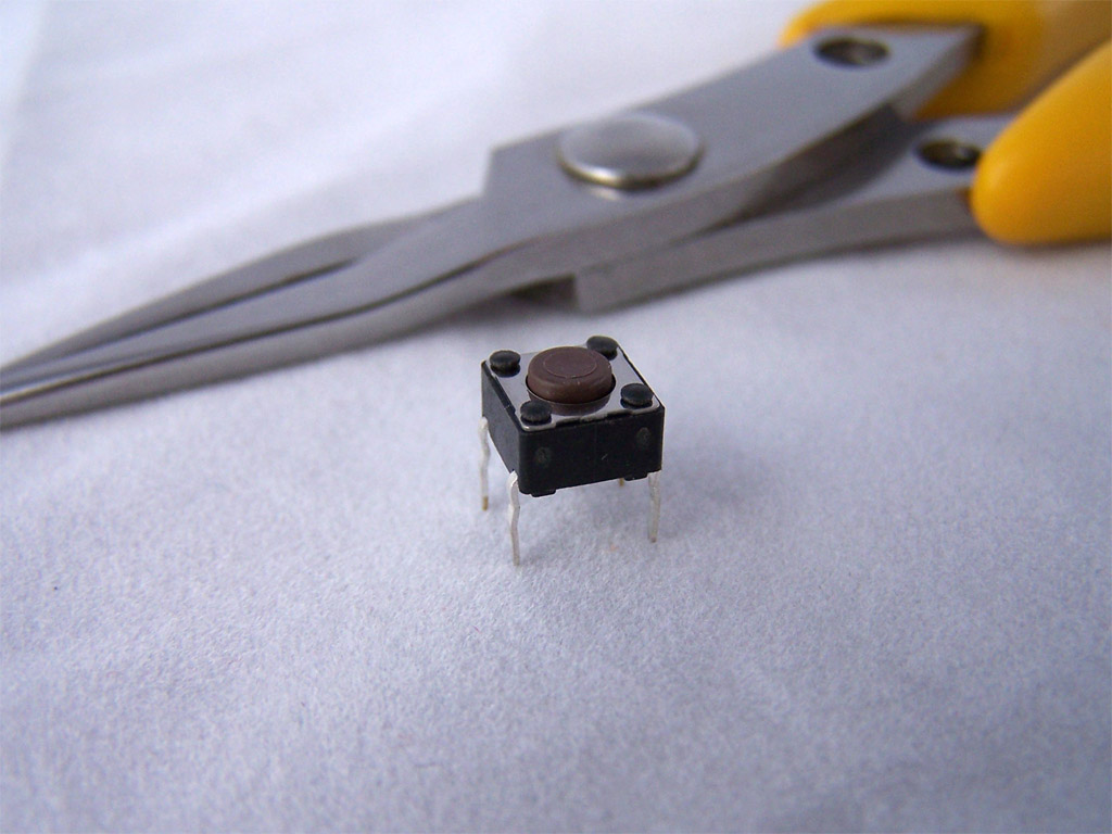
The switch we are using is a . These switches have 2 pairs of pins, with
the pins in each pair connected to each other. This is shown in the diagrams
below.
You will find it useful to straighten the pins on the micro tactile
switch prior to inserting it onto the breadboard. Now we just need to build the
circuit onto the board.
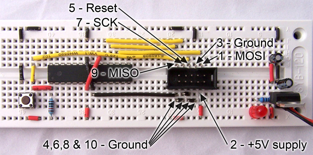
The last stage is to build the ISP (In System Programming) Interface.
This allows for the firmware to be written to the microcontroller using a
programmer, such as the .
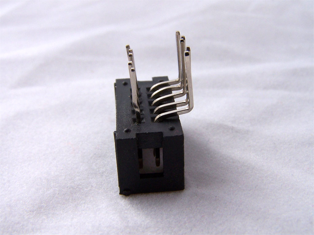
The ISP interface will be via a 10 pin IDC connector (shrouded/box
header), which causes a problem for us. These connectors do not fit onto a
breadboard because the rows are 0.1” (2.54mm) apart. We need the rows to be
0.3” (7.62mm) in order for them to fit on either side of the breadboard center
channel. There are many solutions to this problem. We will be bending the pins
on a . This may not look pretty, but it works.
Lastly we insert the IDC connector then wire it up to 5V supply, ground
and the microcontroller. Care must be taken when inserting the IDC connector,
as the pins are a bit thicker that the wires you would normally insert into a
breadboard.
In ATmega8 breadboard
Circuit – part 3 we will add some I/O devices as well as writing, uploading and
running a simple program.


No comments:
Post a Comment